
Have you ever bought a new lighting kit or other electric mod product and wondered if it even worked before you went through modding it into your case? This little project could save you time and take the guess work out of that question. Having a test PSU will allow you test various modding goodies. Sometimes modders get an idea for a mod and what we want is not available as a modding product. So we need to know if our computer’s PSU will power the device or not. The test PSU can be used to test your device by simply wiring a male molex to it. Because we will be showing a switched PSU, you will have a completely independent and portable 5v and 12v power source. You can take it one step further and make a 7v source as well.
What you will need
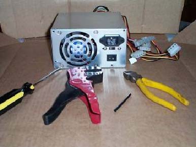
You will need a spare ATX switched PSU. Specs will not matter because you are not powering a whole system. 150watts and up will be plenty. You will also need a screwdriver, wire strippers, wire cutters, and short length of heat shrink tubing.
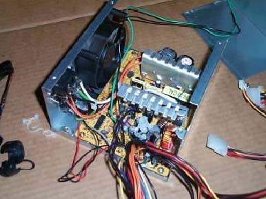
What you do Remove the 4 screws that hold the PSU housing down and remove the housing. Set it aside for re-assembly later.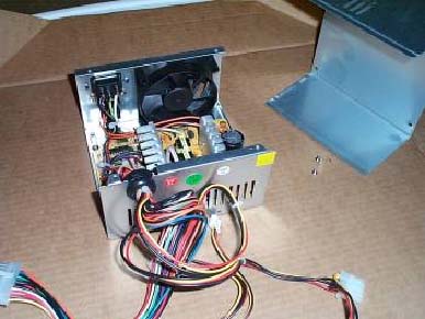
Next, remove the entire wire bundle from where they exit the housing and take apart the rubber grommet and set it aside.
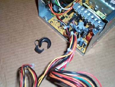
Now separate the molex power wires from the ATX connector bundle and push them off to one side out of the way.
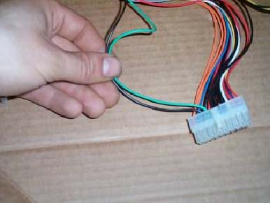
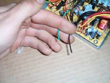
Next, you need to find two wires out of the ATX bundle. These are the wires that normally receive the signal from the motherboard to power up. You need to find the only green wire in the bundle and the black wire directly on it’s left.
Now use your wire cutters and snip them from the ATX connector.
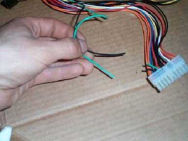
Next place the green and black wire you just snipped out of the way so they do not get snipped by accident in the next step
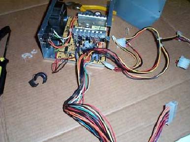
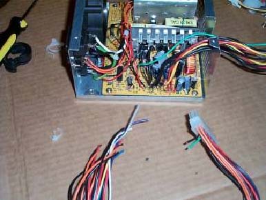
Now, using your wire cutters again, snip the entire ATX wire bundle out of the PSU. Take care that you don’t snip the molex wires, fan wires, switch wires, fuse wires, A/C jack wires, or the green and black wire you cut in the previous step. You should snip the wires as close to the PCB board as you can.
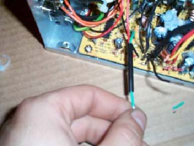
Now snip the green and black wire back to about 3".
Strip both wires back ½" and slide the heat shrink over one of the wires. Twist the two wires together. You may solder them at this point if you choose.
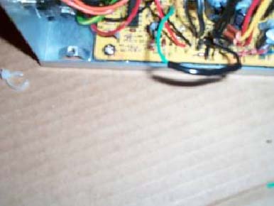
Now slide the heat shrink over the twisted together wires and apply heat to it. A hair dryer works or if you are really daring a lighter will work as well. It should shrink up nice and snug to your connection and shield it from arcing. Once this is done push the wires inside the PSU so that when you replace the cover they won’t bind up or pinch.
Next reinstall the grommet with the molex wires through it and put the housing back together.
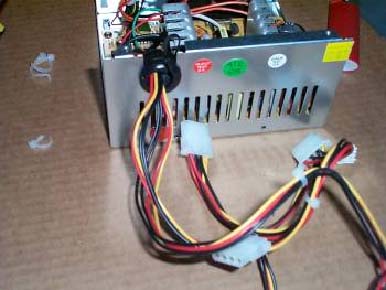
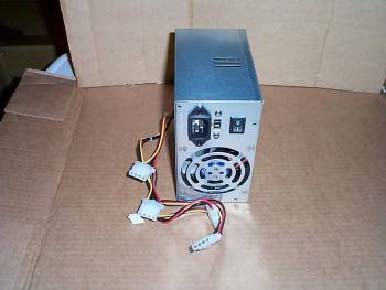
Finally, here you have it. A fully functional, independent, and portable test PSU. Because we used a switched PSU in this project you will be able to use the PSU’s switch to turn it on and off.
Happy Modding
No comments:
Post a Comment